Carrier Rfl 0601el Manual

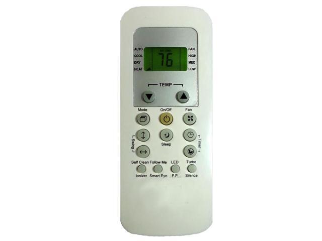
Remote Control FIT Carrier RFL-0601EL A/C Conditioner Condition. Panasonic DMR-EZ48V DVD Recorder Burner VCR HDMI With Remote And Manual. Buy Universal Remote Control Fit For Carrier RFL-0301EH RFL-0601EL Air Conditioner at Walmart.com.
• CONTENTS A FEW WORDS ABOUT YOUR NEW AIR CONDITIONING UNIT ELECTRICAL DATA OPERATING INSTRUCTIONS CEILING UNIT DISPLAY ○ ○ ○ ○ ○ ○ ○ ○ ○ ○ ○ ○ ○ ○ ○ ○ ○ ○ ○ ○ ○ ○ ○ ○. • A FEW WORDS ABOUT YOUR NEW AIR CONDITIONING UNIT Thank you for choosing the Air V, Carrier Recreational Vehicle Air Conditioner, for your cooling needs. You can feel confident in your selection because the same pride in craftsmanship and engineering knowledge. • ’ S GUIDE - 3 OWNER Schematic Diagram of Upper Unit Schematic Diagram of Ceiling Unit. • ’ OWNER S GUIDE - OPERATING INSTRUCTIONS CEILING UNIT DISPLAY TIMER(Orange): When the unit is in reservation on/off timer mode, an orange light will be displayed.
UNIT ON(Green): When the unit is switched on by the remote control or the emergency button, a green light will be displayed. • ’ S GUIDE - 5 OWNER REMOTE CONTROL DESCRIPTIONS Names and Functions of the Buttons TIMER 1. On/Off Button FURN. AUTO COOL HIGH 2.
Although this sounds fine, and since DSOpera doesnt cache anything it should of been fine. As soon as DSOpera came out I jumped on that, for the thrill of being online with my DS. Dsi hacking without flash card. There are some things I can add here however, but I will try to do so swiftly. The memory I got was failty though and the browser froze continuously. The cartridge includes a 8MB GBA RAM card.
Mode Selector Button ON/OFF MODE SPEED 3. Fan Speed Selector Button 4. On Timer Button TEMP.
TIMER TIMER 5. • ’ OWNER S GUIDE - TEMPERATURE SELECTOR BUTTONS - If you set be automatically turned off to stop cooling operation. However, the fan will continue to cir- the desired room temperature, then the unit will culate air even if the compressor is turned off.
Maintain the room temperature at the set temperature. For Two Unit: Install one air conditioner 1/3 and the other air conditioner 2/3’s from front of RV and centered from side to side with referring to compressor delay function. You must apply the compressor delay function (3SEC) to only one of two units. • CAUTION • The air conditioner will not operate if curtains, doors or other materials block the signals from the remote control to the unit.
• If the infrared signal receiver on the unit is exposed to direct sunlight, the air conditioner may not work properly. • ’ OWNER S GUIDE - UNIT OPERATION GENERAL OPERATION PROCEDURE ON/OFF button Press button and the COOL operation is indicated.
- Receiving beeps are heard. - The green UNIT ON lamp of the indoor unit display illuminates.
MODE button Press this button to select the desired operation. • ’ OWNER S GUIDE -10 ENERGY SAVING TIPS Select the temperature setting that suits your comfort needs and leave it at that chosen setting.
Keep the unit’s air filters clean. (See the Normal Maintenance Procedures section of this manual on page 19.) During extreme outdoor temperatures, the heat gain of the vehicle may be reduced by: - parking the vehicle in a shaded area - keeping the windows and doors closed. • ’ OWNER S GUIDE - IMPORTANT Upon installation, the divider must be raised to and sealed with both the bottom of the roof top unit and the sides of the roof opening. The ceiling assembly frame has pin sockets ex- The 115 VAC service for the roof top unit must be tending from the front of the electrical box. • ’ OWNER S GUIDE -12 Figure 1 Figure 2 IMPORTANT Insulating reduces cooling loss and helps prevent water staining of the vehicle ceiling due to moisture condensation.
Registers Supply (cold air) registers should have a minimum discharge area of 48 square inches per system, or 24 square inches per duct. • Figure 4 PREPARATION AND POSITIONING THE ROOF TOP UNIT The roof top air conditioner must be mounted on a level plane from front to rear and side to side when the ve- hicle is parked on a level plane. Figure 4 shows maxi- mum allowable degrees that the Air V can be mounted above or below level. • ’ OWNER S GUIDE - Figure 6 CEILING ASSEMBLY FRAME PREPARATION AND MOUNTING A. Preparation Secure foam topped, three-sided, telescoping divider plate (which is predetermined according to the mea- sured thickness of the ceiling cavity, refer to p. 10) to the divider plate by tightening two screws, reference Figure 2 of page 12. • ’ OWNER S GUIDE - Figure 7 Using the four bolts provided, secure the ceiling assembly frame to the roof top unit. Font adidas 2006 font size.
- понедельник 04 марта
- 67